Basic Information
There are four types of procedures available in EES to examine compact heat exchangers. They apply to a set of heat exchangers that can be grouped into two categories.
All of the compact heat exchangers in the library can be grouped into one of two categories: finned circular tube and plate-fin. Examples of each type are shown below. The flow direction of the fluid under consideration is designated by yellow arrows.
In the plate-fin heat exchanger, b indicates the width of the passages through which the fluid travels. b_1 is the width of passage that fluid being examined passes through. b_2 is the width of the passage on the other flow side. a is the thickness of the plate that divides these passages.
The layout of the non-dimensional compact heat exchanger function is:
Procedure Compact_HX_ND(TypeHX$, Re: f,j_H)
Inputs
TypeHX$ - a representable string variable assigned to the specified heat exchanger surface and geometry
Re - Reynolds number for fluid passing through the minimum cross-sectional area. The Reynold's number can be found as:

where D_h is the hydraulic diameter, mu is the dynamic viscosity, and G is the product of the maximum mass velocity and the density of the fluid. G can be expressed as:
 ,
,
where m_dot is the mass flow rate, sigma is the ratio of the freeflow area to the frontal area, and A_fr is the frontal area.
Outputs
f - the friction factor of the external surface
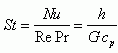
j_H - the Colburn j factor which is a function of the Stanton the Prandtl number:
![]() ,
,
with the Stanton number reducing to:
Example:
Re=3000 "Reynolds number for minimum flow area"
Call Compact_HX_ND('fc_tubes_sCF-70-58J', Re: f,j_H)
The geometry heat exchanger function has two distinct calls based on the type of heat exchanger:
Procedure CHX_geom_finned_tube(TypeHX$: D_i, fin_pitch, D_h, fin_thk, sigma, alpha, A_fin\A)
-Applies to finned tube type heat exchangers including finned circular tubes and finned flat tubes.
Procedure CHX_geom_plate_fin(TypeHX$, a, b_2: b_1, D_i, fin_pitch, D_h, fin_thk, sigma, alpha, A_fin\A)
-Applied to plate-fin type heat exchangers including louvered, pin-fin, strip-fin, plain, and wavy-fin.
Inputs
TypeHX$ - a representative string variable corresponding to the heat exchanger type and surface
a - plate thickness (applies only to plate-fin heat exchangers) [m]
b_2 - thickness of passages through which the second fluid passes (applicable to plate-fin heat exchangers only) [m]
Outputs
D_i - the inside diameter of the tube (applicable to finned circular tubes and pin-fin plate fin) [m]
fin_pitch - the number of fins per meter [1/m] or [1/ft]
D_h - the hydraulic diameter [m] or [ft]
fin_thk - thickness of fins (not applicable to pin-fin) [m] or [ft]
sigma - minimum free flow area/frontal area
alpha - heat transfer area/total volume [m^2/m^3] or [ft^2/ft^3]
A_fin\A - fin area/total area
b_1 - thickness of passages through which the first (considered) fluid passes [m] or [ft]
Notes: For most of the plate-fin geometries there is no inside diameter. The exception is pin-fin plate-fin, which does not have a fin thickness. Likewise, finned-flat tube geometries do not have an associated inside diameter. For the variables in these functions that do not exist, the geometry procedure will return a value of -9999
Example:
a=0.001 [m] "width of divider"
b_2=0.003 [m] "width of passages for second fluid"
Call CHX_geom_plate_fin('sf_plate-fin_s14s-111', a, b_2: b_1, D_i, fin_pitch, D_h, fin_thk, sigma, alpha, A_fin\A)
{Solution:
alpha=673.6 [m^2/m^3]
b_1=0.00635 [m]
D_h=0.003084 [m]
fin_pitch=437 [1/m]
fin_thk=0.000152 [m]
sigma=0.5193 }
The heat transfer function has two distinct calls akin to the geometry function.
Procedure CHX_h_plate_fin(TypeHX$, a, b_2, m_dot, A_fr, Fluid$,T, P:h)
-Applies to plate fin type heat exchangers including louvered, pin-fin, strip fin, plain, and wavy.
Procedure CHX_h_finned_tube(TypeHX$, m_dot, A_fr, Fluid$,T, P:h)
-Applies to finned circular and finned flat tubes.
Inputs
TypeHX$ - a representative string variable corresponding to the heat exchanger type and surface
a - plate thickness (applies only to plate-fin heat exchangers) [m] or [ft]
b_2 - thickness of passages through which the second fluid passes (applies only to plate-fin heat exchangers) [m] or [ft]
m_dot - mass flow rate of fluid through considered passage [kg/s] or [lbm/hr]
A_fr - frontal area of heat exchanger [m^2] or [ft^2]
Fluid$ - type of fluid
T - temperature of fluid in either [C], [K], [F] or [R]
P - inlet pressure in [Pa], [kPa], [MPa] or [psia]
Outputs
h - average coefficient of heat transfer [W/m^2-K]
Example:
$UnitSystem SI K Pa J
m_dot=2 [kg/s] "mass flow rate of fluid"
A_fr=0.3 [m^2] "frontal area of heat exchanger"
Fluid$='air' "fluid type"
T=400 [K] "mean temperature of fluid"
P=101300 [Pa] "inlet pressure"
b_2=0.0063 [m] "width of passages for second fluid"
a=0.0001 [m] "width of divider"
Call CHX_h_plate_fin('wf_plate-fin_s178-38W', a, b_2, m_dot, A_fr, Fluid$,T, P:h)
{Solution:
h=190.1 [W/m^2-K]}
The DELTAp function also has distinct calls for plate-fin and finned tube heat exchangers:
Procedure CHX_DELTAp_finned_tube(TypeHX$, m_dot, A_fr, L, Fluid$, T_i, T_o, P: DELTAp)
-Applies to finned circular and finned flat tubes.
Procedure CHX_DELTAp_plate_fin(TypeHX$, a, b_2, m_dot, A_fr, L, Fluid$, T_i, T_o, P: DELTAp)
-Applies to plate-fin type heat exchangers, including louvered, pin-fin, strip-fin, plain, and wavy.
Inputs
TypeHX$ - a representative string variable corresponding to the heat exchanger type and surface
a - plate thickness (applies only to plate-fin heat exchangers) [m] or [ft]
b_2 - thickness of passages through which the second fluid passes (applies only to plate-fin heat exchangers) [m] or [ft]
m_dot - mass flow rate of fluid through considered passage [kg/s] or [lbm/hr]
A_fr - frontal area of heat exchanger [m^2] or [ft^2]
L - length of the heat exchanger in the flow direction [m] or [ft]
Fluid$ - type of fluid
T_i - temperature of inlet fluid in either [C], [K], [F] or [R]
T_o - temperature of exit fluid in either [C], [K], [F] or [R]
P - inlet pressure in [Pa], [kPa], [MPa], or [psia]
Outputs
DELTAp - pressure drop in [Pa] or [psia]
Notes:
Pressure drop for plate-fin heat exchangers does not include end effects due to compression and expansion of fluid. These effects are usually negligible and on the same order as pressure drop due to flow acceleration. The majority of the pressure drop is due to core friction. The core friction accounts for upwards of 90% of the total pressure drop in most cases. This limitation does not apply to finned tube heat exchangers, as the friction factor accounts for the additional pressure drop at the entrance and exit.
Example:
$UnitSystem SI Pa K J
a=0.0001 [m] "width of divider"
b_2=0.0063 [m] "width of passages for second fluid"
m_dot=2 [kg/s] "mass flow rate of fluid"
A_fr=0.3 [m^2] "frontal area of heat exchanger"
Fluid$='air_ha' "fluid type"
T_i=300 [K] "entrance temperature"
T_o=400 [K] "exit temperature"
P=101300 [Pa] "inlet pressure"
L=0.15 [m] "length of heat exchanger"
Call CHX_DELTAp_plate_fin('p_plate-fin_s1477', a, b_2, m_dot, A_fr, L, Fluid$, T_i, T_o, P: DELTAp)
{Solution
DELTAp=364.2 [Pa]
}
All of the results for these procedures are based off of experimental data presented in Kays and London (1984).