HelicalPipeFlow_local

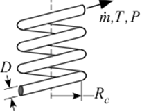
Procedure HelicalPipeFlow_local(Fluid$, T, P, m_dot, D, x,RelRough,R_c: h_T, h_H, dPdx) returns lower and upper bounds on the local heat transfer coefficient and the pressure gradient for a specified mass flow rate (m_dot) through a circular tube of diameter D at position x that is wound in a helix with radius R_c. The procedure modifies the results for a straight tube (obtained using the procedure PipeFlow_local) as discussed in the Heat Exchanger Design Handbook and Barron (1999). Properties are evaluated at the bulk temperature T and pressure P, for all built-in fluids except brines, for which the concentration in mixtures with water is provided in % in place of pressure. Units of the inputs and outputs depend upon the unit settings in EES.
Inputs:
Fluid$ can be any fluid in the EES database. The fluid can be an ideal gas, a real fluid, a brine, or an incompressible fluid.
T - the bulk temperature of the fluid in [C], [K], [F], or [R].
P - pressure can be in [Pa], [kPa], [bar], [MPa], [atm], or [psia]. (Note that for brines, this parameter provides the concentration in %)
m_dot - mass flow rate in [kg/s], or [lbm/hr]
D - diameter of the tube in [m] or [ft]
x - axial position in the tube in [m] or [ft]
RelRough - the ratio of the dispersions on the wall of the tube to the tube diameter (must be between 0 and 0.05)
R_c - the radius of the helical winding in [m] or [ft]
Outputs (all but the first output are optional):
h_T - heat transfer coefficient in [W/m^2-K] or [Btu/hr-ft^2-R] assuming that the pipe wall is at constant temperature (lower bound)
h_H - heat transfer coefficient in [W/m^2-K] or [Btu/hr-ft^2-R] assuming a constant heat flux at the pipe wall (upper bound)
dPdx - pressure gradient in the pressure units set in the EES Unit System dialog
Notes
This procedure calculates the Reynolds and Prandtl numbers and then calls the procedure HelicalPipeFlow_N. HelicalPipeFlow_N_local calls the straight tube procedure PipeFlow_N_local and modifies the results to account for the curvature. The straight tube friction factor is modified as discussed in the Heat Exchanger Design Handbook (2008) in order to account for curvature. The straight tube Nusselt number is modified as discussed in Barron (1999) in order to account for curvature.
Two values of the heat transfer coefficient are returned. The first, h_T is determined assuming that the wall is at constant temperature. The second is determined assuming that the wall is subjected to a constant heat flux. For laminar flow, these values should provide lower and upper bounds on the heat transfer coefficient. For turbulent flow, these values are identical.
Example 1:
$UnitSystem SI Pa J K m
Fluid$='Water'
T=300 [K]
P=200000 [Pa]
m_dot=1 [kg/s]
D=0.05 [m]
L=5 [m]
RelRough=0.001 [-]
R_c=0.2 [m]
CALL HelicalPipeFlow_local( Fluid$, T, P, m_dot, D, L,RelRough,R_c: h_T, h_H, dPdx)
{Solution:
h_H=4068 [W/m^2-K]
h_T=4068 [W/m^2-K]
dPdx=-661.6 [Pa/m]
}
Example 2:
$UnitSystem SI Pa K J
T=363 [K] "average temperature of fluid in duct"
C=50[%] "concentration of the propylene glycol-water solution"
m_dot=0.10 [kg/s] "flow rate"
D=0.025 [m] "inner pipe diameter"
L=5 [m] "length"
RelRough=0.005 [-] "relative roughness"
R_c=0.2 [m]
CALL HelicalPipeFlow_local('PG', T, C, m_dot, D, L,RelRough,R_c: h_T, h_H, dPdx)
{Solution:
h_T=1153 [W/m^2-K]
h_H=1153 [W/m^2-K]
dPdx=-41.55 [Pa/m]}