DuctFlow

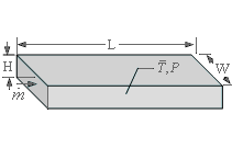
Procedure DuctFlow( Fluid$, T, P, m_dot, H, W, L, RelRough: h_T, h_H, DELTAP, Nusselt_T, f, Re) returns a lower and upper bound on the average heat transfer coefficient and the pressure drop for mass flow m_dot through a rectangular duct of height H, width W, and length L. The procedure is applicable for simultaneous hydrodynamic and thermally developing flow or for fully-developed flow in the laminar, transitional or turbulent flow regimes. Properties are evaluated at a bulk temperature T and pressure P and used to calculate the Reynolds and Prandtl numbers. Units of the inputs and outputs depend upon the unit settings in EES.
Inputs:
Fluid$ can be any fluid in the EES database. The fluid can be an ideal gas, a real fluid, a brine, or a fluid from the Solid-Liquid property library.
T - the bulk temperature of the fluid in [C], [K], [F], or [R].
P - pressure can be in [Pa], [kPa], [bar], [MPa], [atm], or [psia]. (Note that for brines, this parameter provides the concentration in %)
m_dot - mass flow rate in [kg/s] or [lbm/hr]
H - duct height [m] or [ft]
W - duct width [m] or [ft]
L - length of the duct [m] or [ft]
RelRough - the ratio of the dispersions on the walls of the duct to the hydraulic diameter of the duct (must be between 0 and 0.05). The hydraulic diameter is 2 W H/(W + H).
Outputs:
h_T - heat transfer coefficient in [W/m^2-K] or [Btu/hr-ft^2-R] assuming that the duct wall is at constant temperature (lower bound)
h_H - heat transfer coefficient in [W/m^2-K] or [Btu/hr-ft^2-R] assuming a constant heat flux at the duct wall (upper bound)
DELTAP - pressure difference between the inlet and outlet of the duct in the pressure units set in the EES Unit System dialog
Nusselt_T - Nusselt number determined for a constant temperature duct wall
f - friction factor [-]
Re - Reynolds number [-]
Notes:
This procedure calculates the Reynolds and Prandtl numbers and then calls DuctFlow_N, which determines the Nusselt numbers associated with constant temperature and constant flux.
Two values of the heat transfer coefficient are returned. The first, h_T is determined assuming that the wall is at constant temperature. The second is determined assuming that the wall is subjected to a constant heat flux. For laminar flow, these values should provide lower and upper bounds on the heat transfer coefficient. For turbulent flow, these values are identical.
The procedure will determine if the flow is laminar or turbulent. Transitional flow is assumed to occur for Reynold's numbers between 2300 and 3000 and interpolation is applied between the laminar and turbulent correlations.
The value of the heat transfer coefficient that is returned by this procedure is applicable for simultaneous development of the thermal and hydrodynamic boundary layers in the laminar flow regime. See Section 5.2.4 of Nellis and Klein for more information.
The Graetz number (Re Pr D / L) is used to determine the correction for developing flow assuming a simultaneous thermal and hydrodynamic development; set L to a large number if developing flow corrections are not applicable.
Example:
$unitSystem SI Pa K J
T=363 [K] "average temperature of fluid in duct"
P=101300 [Pa] "pressure of air in duct"
m_dot=0.005 [kg/s] "flow rate"
H=0.1 [m] "duct height"
W=0.5 [m] "duct width"
L=5 [m] "duct length"
RelRough=0.005 [-] "relative roughness"
call DuctFlow('air',T,P,m_dot,H,W,L,RelRough:h_T, h_H ,DELTAP, Nusselt_T, f, Re)
{Solution:
DELTAP=0.02058 [Pa]
f=0.1334 [-]
h_H=1.429 [W/m^2-K]
h_T=1.051 [W/m^2-K]}
Note that it is not necessary to evaluate all outputs for versions 9.513 or newer. For example, if only h_H is of interest, the call statement can be:
call DuctFlow('air',T,P,m_dot,H,W,L,RelRough:, h_H, , , , )
In the European system use the semicolon in place of the comma as the list separator.