Contents
Evaporator2_CL
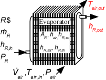
Evaporator2_CL determines the outlet air and refrigerant states for heat exchange between air and an evaporating refrigerant. The refrigerant may exit in a two-phase state or superheated, depending on the area and heat transfer coefficients supplied to the routine. No consideration is provided for condensation or frost formation in this routine. It is necessary to provide the heat transfer coefficients on the air side of the heat exchanger and for the saturated, and superheated sections on the refrigerant side. There heat transfer coefficients can be determined using the functions in the Heat Transfer Library, as illustrated in the example.
This library file can be used to calculate the outlet state of the of the evaporator with specified heat transfer area. Use Evaporator1_CL to determine the required area at design conditions.
Reference: Heat Transfer, Nellis and Klein, 2009, Cambridge University Press, section 8.5
Inputs:
R$: name of the refrigerant
m_dot_R: refrigerant flow rate (kg/s, lbm/hr)
h_R_in: refrigerant inlet specific enthalpy (J/kg, kJ/kg, Btu/lbm)
P_R: refrigerant pressure (Pa, kPa, bar, MPa, psia, atm)
V_dot: volumetric flow rate of air (m^3/s, cfm)
T_air_in: air inlet temperature (C, K, F, R)
P_air: air pressure (Pa, kPa, bar, MPa, psia, atm)
h_air: effective outside (air) heat transfer coefficient per unit refrigerant tube area (W/m^2-K, Btu/hr-ft^2-R)
A_air\A_R: ratio of effective heat transfer area on the air side to the heat transfer area for the refrigerant*
h_R_SH: heat transfer coefficient for refrigerant in the superheat regime (W/m^2-K, Btu/hr-ft^2-R)
h_R_sat: average heat transfer coefficient for refrigerant in the saturated section (W/m^2-K, Btu/hr-ft^2-R)
h_sh: average heat transfer coefficient for refrigerant in the superheated section (W/m^2-K, Btu/hr-ft^2-R)
A_R: required heat transfer area for the refrigerant (m^2, ft^2)
Outputs:
Q_dot: overall heat transfer rate (W, kW, Btu/hr)
h_R_out specific enthalpy of exiting refrigerant (J/kg, kJ/kg, Btu/lbm)
T_air_out: outlet temperature of the air (C, K, F, R)
*A_air\A_R is the ratio of the product of the overall fin efficiency and total (finned and unfinned) area on the air side to the total surface area inside the refrigerant flow passages. For unfinned surfaces, A_air\A_R is the ratio of the outer surface to inner surface areas.
Example:
$UnitSystem SI C kPa mass kJ
$TabStops 0.2 4 in
R$='R134a' "refrigerant"
m_dot_R=0.008 [kg/s] "refrigerant flow rate"
T_cond_out=38 [C] "condenser exit temperature"
P_cond=1 [MPa]*convert(MPa,kPa) "condenser pressure"
h_cond_out=enthalpy(R$,T=T_cond_out,P=P_cond) "specific enthalpy of refrigerant exiting condenser"
P_R=175 [kPa] "evaporator pressure"
T_R_sat=T_sat(R$,P=P_R) "evaporator saturation temperature"
h_R_in=h_cond_out "specific enthalpy of refrigerant entering evaporator"
x_R_in=quality(R$,h=h_R_in,P=P_R) "inlet quality"
T_air_in=5 [C] "air inlet temperature"
P_air=101.3 [kPa] "air inlet pressure"
V_dot_air=0.08 [m^3/s] "volumetric flow rate of air"
h_R_sat=h_boil "convection coefficient for saturated R134a - see calculation of h_cond below"
h_R_sh=h_T_sh "convection coefficient for superheated R134a. See calculation of h_T_sh below"
h_air=h_air1 "convection coefficient for air. See calculation of h_air1 below"
A_air\A_R=A_air\A_R1 "ratio of area on the air side to that on the refrigerant side"
A_R=0.25 [m^2] "total surface area on refrigerant side"
Call Evaporator2_CL(R$, m_dot_R, h_R_in, P_R, V_dot_air, T_air_in, P_air, h_air, A_air\A_R, h_R_sat, h_R_sh, A_R : Q_dot, h_R_out, T_air_out)
T_R_out=temperature(R$,h=h_R_out,P=P_R)
"!Calculation of the heat transfer coefficients using the Heat Transfer Library functions"
N_circuits=1 "number of parallel circuits"
A_fr=0.26*0.2 [m^2] "frontal area"
W=0.2 [m] "length of tubes"
N_tubes=A_R/(pi*W*D_in) "required number of tubes"
Call CHX_geom_finned_tube('fc_tubes_s80-38T': D_o, fin_pitch, D_h, fin_thk, sigma, alpha, A_fin\A) "air side geometry"
"Determine ratio of area on air side to the refrigerant heat transfer area"
th = 0.9 [mm]*convert(mm,m) "tube wall thickness"
D_in=D_o-2*th "inner tube diameter"
A_unfinned=pi*D_o*N_tubes*W*(1-fin_thk*fin_pitch) "unfinned area on air side"
A_tot=A_unfinned+A_finned "total finned and unfinned area on air side"
A_finned/A_tot=A_fin\A "ratio of finned to total area is provided by Compact HX library"
eta_o=0.97 "overall fin efficiency - See Heat Transfer, Nellis and Klein, section 8.5"
A_air\A_R1=eta_o*A_tot/(N_tubes*W*pi*D_in) "ratio of heat transfer area on air side to that on refrigerant side"
"Determine heat transfer coefficients for air and refrigerant "
m_dot_air=V_dot_air/volume(air,T=T_air_in,P=P_air) "air mass flow rate"
Call CHX_h_finned_tube('fc_tubes_s80-38T', m_dot_air, A_fr, 'Air', T_air_in, P_air: h_air1) "compact hx correlation"
call PipeFlow('R134a',T_R_sat+1 [C], P_R, m_dot_R/N_circuits, D_in, W, 0: h_T_sh, h_H_sh, DELTAP_sh, Nusselt_T_sh, f_R_sh, Re_R_sh) "superheat section"
T_w=T_air_in "estimated wall temperature"
G=m_dot_R/N_circuits/(pi*D_in^2/4) "mass velocity"
q``=Q_dot/A_R*convert(kW/m^2, W/m^2) "heat flux"
h_boil=Flow_Boiling_avg(R$, T_R_sat, G, D_in, x_R_in, 1, q``, 'Horizontal') "saturated section"
{Solution
A_air\A_R1=12.13 [-]
h_air=53.21 [W/m^2-K]
h_R_sat=1001 [W/m^2-K]
h_R_sh=315.7 [W/m^2-K]
Q_dot=1.132 [kW]
T_R_out=-8.313 [C]
T_R_sat=-13.42 [C]
T_air_out=-6.109 [C]
}
Index